After briefly encountering EPROM processors when working for Sinclair Research Ltd in Cambridge, hardware electronics designer, Brian Flint, began using the processors to solve design problems, later using PIC devices for similar purposes. He explains how he found practical, and occasionally unique, ways to exploit both the EPROM and the PIC, and discusses their relative pros and cons.
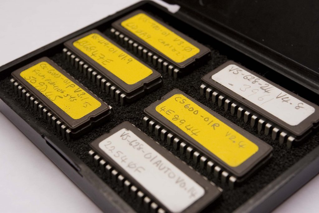
Brian’s box of EPROMs. The label covers the light hole to prevent accidental data loss
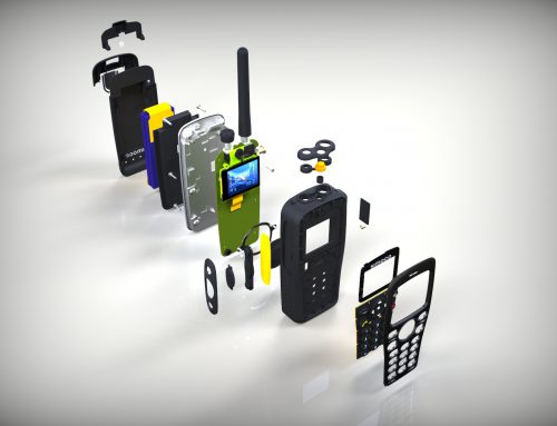
The acronym EPROM stands for Erasable Programmable Read Only Memory, and refers to a memory chip used in electronics from the early 1970s onwards. EPROM memory chips have an advantage over standard microchips, in that they can be removed from their sockets and programmed to act as Read Only Memory devices. It is also possible to wipe their memory of data – by shining ultraviolet light through a tiny hole on the top for a certain length of time – so that they are can be programmed afresh. This characteristic enables engineers to update their program data whenever necessary.
Brian Flint, who worked at Sinclair Radionics Ltd from 1971 to 1979 and then at Sinclair Research Ltd as project leader for the hardware design aspect of the ZX80 and ZX81 home computers, first encountered EPROMs during his Sinclair days. But it was as chief design engineer for video duplication specialists, Dwight Cavendish Ltd, that he began incorporating them into his design hardware. He explains when and how he became familiar with the technology.
“I became aware of EPROMs when they first came out, I suppose, in the early 1970s, but I think my first experience with them was when I was programming some memory devices at Sinclair. We had an EPROM in the ZX80, although for the production models it was probably replaced by a standard ROM, which you can’t reprogram, but I can’t quite remember.
“Whenever the ZX80 program was changed the EPROM also had to change because it contained the program. The microprocessor in the ZX80 ran off of the program so the most convenient thing was to put the code in an EPROM because you can reprogram them. If you changed anything – if there was a bug fixed – it would mean a new EPROM or update. I didn’t write code then, so some software person would release the update and I would make sure the ZX80 I was testing had the latest version. I must have had a master and copied the program from that but I can’t really remember much about it now.”
It was a few years later, while working for Dwight Cavendish Ltd in St Neots, that Brian encountered a problem which he decided would be best solved by using EPROM processors.
“When I was at Dwight Cavendish we were using an infrared remote control to operate multiple domestic VCRs,” Brian recalls. “We were breaking open remote control handsets, taking the boards out and putting them into this little box. Then if we hit the record button on the control panel, it would effectively close the switch contracts and trigger record on this board. The board would then generate the record signal electrically, and we would take that electric signal and spread it over to lots of infrared transmitter diodes which controlled the rest of the VCRs.
“The problem was that customers had many different makes of VCR. There was Sanyo, Panasonic, Akai, Sony – all sorts of different makes – and some VCRs from the same manufacturer had different codes and hand units. We continually had to break remotes open and trace out their circuits to work out how to wire them into our interface, and it was getting impossible because it was not easy to connect to some of these things.
“So I thought what we needed to do was decode the signal that came out of the hand units and generate it ourselves with a little program. To make that possible we needed some means of storing all the different manufacturer’s codes. It is the same sort of thing you get with a universal hand unit that you can buy now, which can be programmed with all the different manufacturers’ codes. So basically I was doing that.
“So I would get hold of a hand unit, press the various buttons on it and use an infrared light sensor to catch the signal and work out what all the timing parameters were. I would measure the time pulses and I had a little code that I wrote that would recreate that signal.
“Eventually we were sending customers an interface with a little switch on it and we gave instructions to switch it to Position 1 for Sony, 2 for Panasonic, 3 for Akai, or something like that.
“So there was a need to solve a problem and that forced us to make this little board. That was mainly to control VCRs, but once I’d got the program working for that I expanded into writing code to do other things. Once you’d got the knack of how to do it you can expand it to all sorts of areas.”
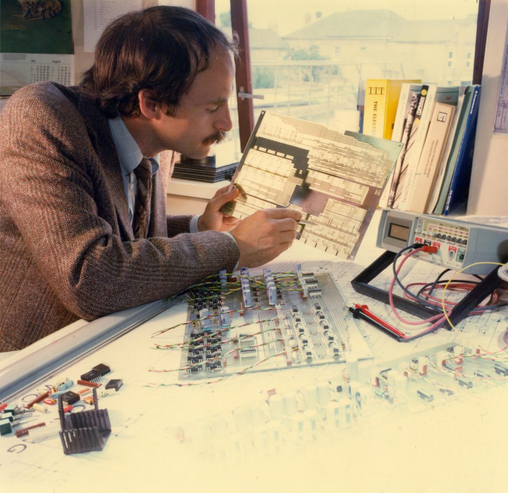
A promotional picture taken of Brian during his Dwight Cavendish days
Method and Equipment
Before Brian could start working with ERPOMs he needed to get hold of the necessary equipment to program them. The device he chose was a Dataman S4 handheld programmer. The device, which is about the size of a large pocket calculator and originally shipped with a 95-page manual, is equipped with a ZIF (Zero Insertion Force) socket and accompanying lever for attaching the EPROM that is to be programmed, 48 soft keys and a small, four-line, 80-character, LCD display. The user can either enter their code using the on-board keypad, or connect the S4 to a computer using an RS232 cable and download their program data from the computer.
Brian explains a little more about how he worked with the device.
“I would write the code in what’s called assembler language, and I would assemble it, if you like, in my head. When I say I’d do it in my head I mean I would write it out using a pencil and paper! Then I’d then convert that into what is called the object code, which is a lot of hexadecimal figures; so I would work out what the hexadecimal code was for each line and hand-punch the numbers into my Dataman S4 programmer using its mini keyboard.
“I mostly did it that way, rather than use an assembler on a computer, because the programs weren’t all that big and you could enter many hundreds of lines of code in a few hours. Then I would stick a blank EPROM in, burn it and then test it.
“The S4 was about £500, I think, and I bought it through work. I could spend that sort of money for R&D purposes and didn’t have to ask permission. Of course, when I started using the Dataman in the early 1980s, if you wanted to buy a computer they’d cost about £1200, which was a considerable amount in those days as the cost of living has gone up by about three-and-a-half times since then. Plus you would have to get all the software to go with it to do what you needed, and there was the learning curve too – you had to learn all this other stuff and get it all working together.
“When you got hold of a little Dataman, on the other hand, all you needed to do was read the instruction book, work out what you wanted to do and get on with it. You ended up with the same product whether you used a Dataman or a computer; it was just a means of creating the code, that’s all. You could even download code to it from a computer rather than type it in using the little keyboard.”
When Brian began working with EPROMs, he had had no formal training in software code programming, although he had learnt a little bit about it over the years. He first dabbled with code when working for Sinclair Research in King’s Parade, Cambridge, just after Clive Sinclair started up his new business which would soon produce the Sinclair ZX80, ZX81 and Spectrum computers.
“I’d been fiddling around with a little bit of code when I was at Sinclair Research,” recalls Brian, “using the Science of Cambridge MK14 board. The MK14 was something that Chris Curry had been working on but he’d moved out to set up Acorn by then. At the time we moved into King’s Parade, Sinclair Research hadn’t made anything, but there were customer returns of the MK14 so I was fixing them. While I was doing that I’d fiddle around with them – program them – and learnt a bit. I was just messing around with code for my own amusement, really.
“The purpose of the MK14 board was to be an educational thing. If you wanted to make a digit flash on and off, for example, you could use the MK14 to write a little routine to make that happen. It had a little display on it and you could enter some data in hexadecimal form, I think, and get it to do some silly little routines – little simple things.”
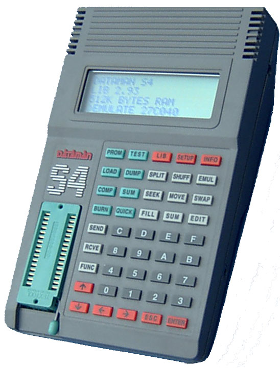
Dataman S4 EPROM programmer. Thanks to Daniel Smith at Dataman for providing this image
Getting Started
Before Brian could start writing code for his Dwight Cavendish projects, he first had to select the most suitable EPROM to program, and there were a number of products to choose from. He explains what he used and how things progressed from there on.
“I had to choose the processor and the one I picked was an Intel 8032 8-bit microprocessor, I think. I simply chose that one because it was supposed to be good. So I got a book on how to write the assembler language for it, worked out how the memory was organised and what the various basic instructions were.
“When I’d read that through I started applying the problem I had to it. Once you have an objective to aim for, it is odd how very quickly you find you can do something. If you are just aimlessly messing around you will only go so far. But once you have a specific task in mind, within a matter of weeks, or maybe less, you can get something up and working. You might have do a little bit of debugging and further work on it but you’d be amazed how fast you progress.
“There are different assembler languages for each microprocessor. It’s like Heinz 57 varieties – they’ve all got different ways of doing things – but there are a lot of things they have in common too. There was a paper-back book I bought back in the 1970s, all about how microprocessors work, which I’d read through, and that really gave an insight into it all. You’ve just got to learn how microprocessors work and become acquainted with software to a certain level.
“Ultimately the processor runs off of noughts and ones, but you start off with writing things down in a semi-English way. If you wanted it to load a value into a memory location you might actually use the word Load and then you have some way of identifying the memory location. Then you’d tell it to move to the next memory location. You might want to load the memory contents at that address into the accumulator, so there would be an instruction for that. So you look up the hexadecimal conversion for that type of load from that type of memory place. Then there is an instruction which loads the accumulator into memory and that will be slightly different.
“The instruction book gave you an example and you’d just follow that. You very quickly learn what they are because you are using them all the time and eventually you learn all the codes off by heart.”
Divide and Conquer
Brian explains how he decoded the signals sent by the infrared VCR hand controls and the method he used to deal with that data when creating code for the EPROM.
“What I did for the remote control code was devise what you might call an algorithm, or at least a way of splitting up these infrared pulses. I think I was using multiples of 50 microseconds. I would measure the width of a pulse, which was the length of time the infrared transmitter would be lighting up for. Then I would calculate how many times 50 microseconds went into it. So if the pulse was one millisecond there would be 20 lots of 50 microseconds going into it. I would enter 20 into a data table, or rather the hexadecimal value for 20, and I’d build up this table of data.
“The program would basically run through, get a value and say to itself, ‘I’ve got to light the infrared beam for 20 lots of 50 microseconds.’ There would be a little loop that counted 20 lots and then switched the LED on. After that it would get to the next one and say ‘Oh, I’ve got to switch it off for this amount of time.’ So I had a little system I worked out for measuring times.
“It would know when it had got to the end of the table because there would be some marker. There might be more pulses in one type of system than another, in which case when it got to the end there would be some code that told it to repeat the whole lot again. For example, the instruction would tell it to repeat five times, or something like that, even though the user pressed the button once.
“And in the code there would be a switch that pointed to the beginning of the relevant data table relating to the particular operation or VCR. There were codes for stop, rewind, play, fast forward, eject and I’d worked them all out and had them sitting in a certain position relative to one another in a table.
“A good part of the EPROM was storing data while another part of it was actually running the code. So the code would reside in one part of the EPROM, the program in another.
“It was all pretty simple in a way. Once you had worked something out in your head you could write a little program for it which wasn’t terribly difficult.”
Now that most of us are accustomed to viewing data on a large monitor screen, it is hard to imagine how engineers managed to check code for errors on a screen as small as that of the S4. Of course, there were ways, as Brian explains.
“You are making errors all the time but if something doesn’t work you can spot it. Debugging software can be done in different ways. You can make the code run a little way through and then deliberately stop, and if it continuously crashes in that section you know roughly where there is a problem. But if it can run that bit of the code you know the section is fine.
“Or you can enter some code so that when it gets to a certain point it flashes a little LED on and off and then you can visually check that the LED is flashing. So you do little tests and develop tricks to find out if it is running so far and find out if it manages one bit but misses another.
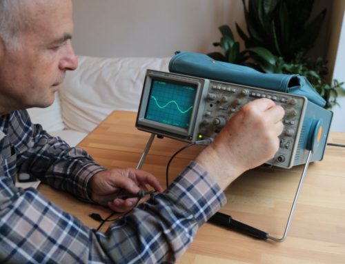
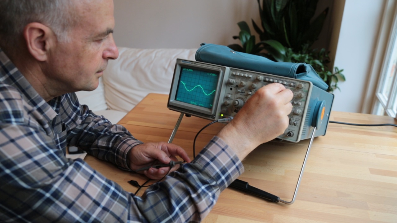
“You can also test a lot of things by looking at the signal on an oscilloscope to see if the waveforms looked more or less right. You know what you are after.”
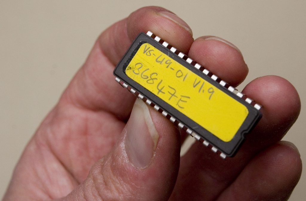
It is always useful to label chips
EPROMs in Action
Once Brian realized that EPROMs were a great way to solve certain electronic design problems, he began using them more and more. By working in this way, the software and hardware were being developed in unison, and this meant that the use of both technologies was optimised. Brian describes how his work with EPROMs progressed.
“What happened was the entire product range of the company became microprocessor based rather than just logic, so I started putting microprocessors into everything. I’d usually have one unit communicating with another via a RS232-type control system.
“RS232 is a protocol for sending 8-bit word data. It’s a standard way of formatting data and you can put it into a dumb terminal, as we call it, so it will read the data up on screen so you can debug it easily. So in our video duplication systems, for example, we had lots of interconnected VCRs and I’d be using that communication system to connect them. As well as RS232, I also used I²C, which is another serial communication format, devised by Philips. It communicates in both directions up one wire, so it is bi-directional and doesn’t have a separate clock.
“In practice, you have something that sends out a signal over I²C and when it has finished sending out that stream, it sits and waits for a reply. When the reply comes in it sends again. So using that system connected devices can communicate with each another and send information.
“Ultimately all the products, up to a very sophisticated level, were done like that. To do automatic quality control I had a load of boards communicating with a PC, which was controlling the video machines. I was reading signals off of VCRs, doing an A-D conversion, sending it to a computer which would draw pictures of the RF signal and audio levels and that was all being stored in a Microsoft Access database. It could test up to 1000 tapes an hour automatically.
“In a system there might be 10 to 15 different products all with different codes in them, all communicating with each other and with a PC, using a high-ish rate of data transfer. That’s what it all led up to after eight or 10 years of progress.”
The video duplication systems made by Dwight Cavendish were installed in countries all over the world, which meant that Brian was often flying abroad to sort out installation issues and oversee product updates. On such occasions, he found it very helpful to be able to reprogram EPROMs on site using the eminently portable Dataman S4. He recalls the time he was working at Fuji Magnetics in Germany, where a system involving Sony VCRs needed on-site tuning.
“That was a semi-automatic system for video duplication. It was controlling these one-inch tape machines via an RS424 remote control. I didn’t have one of those exact VCR models in the lab at work to test my code with, so I tested it on another machine that had a similar sort of protocol. Using that I wrote the basic code but wasn’t certain if it would fully work with the model Fuji Magnetics were using because there are always differences between machines and they can respond slightly differently. For example, there was a Sony protocol that controlled Sony machines, but the individual models have different response times and supplementary control signals. We could control our Sony VCR in a certain way but another machine, which is reeling big one-inch tapes around, will have slightly different dynamics.
“Most of it had been tested but there were some slight unknowns and I didn’t know how it would work until the system was connected up to the machines they were using. When I got out there I found that most of what I had done was working but there were some little hitches and I had to try and figure it out on the spot and then write some code there and then, which I managed to do.
“I took some blank EPROMs with me but when I had used those up I needed them wiped clean so that I could reprogram them, and Fuji Magnetics happened to have an ultraviolet box which could wipe the contents.
“I also took the Dataman with me and all my code, which was hand-written on sheets of paper and just kept in a folder. I always liked to have a master code to refer back to so I had a lead pencil with a rubber on the end and anything that got changed I would rub out on the master sheets and re-write in so that I could see exactly what I’d done. I was constantly buying Papermate non-stop pencils with a rubber on the end – I couldn’t exist without one of those!” TF
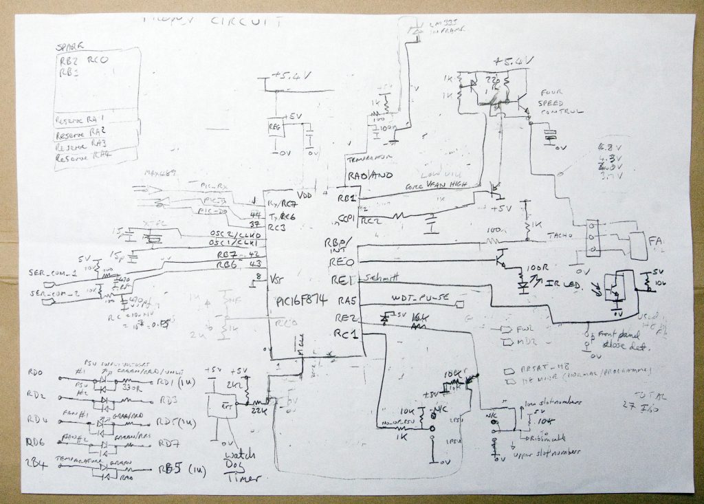
One of Brian’s working drawings, showing lots of rubbing out
Part 2 of Using EPROMs and PICs can be found here: Part 2
