In Part 1, Brian explained how he came to use EPROMs in his designs and why they were particularly effective solutions. In Part 2 he discusses PICs and his use of them, describing how he programmed them in unorthodox ways to achieve extra functionality. He also recalls the time he created a system to power an unusual art exhibition.
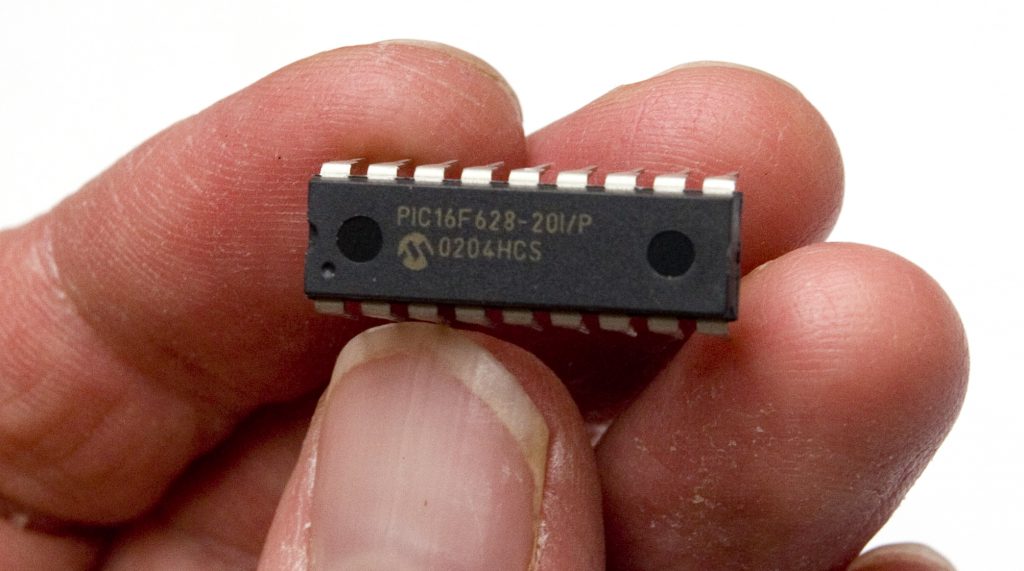
PICs are very small and neat!
The Peripheral Interface Controller
Electronic component design and manufacture is highly competitive, and clearly a lucrative business for companies such as Intel, Texas Instruments and many others. One such developer, called Mircrochip Technology successfully marketed an alternative to the EPROM, which is known as a Peripheral Interface Controller, or PIC for short. Brian eventually moved from using EPROMs to PICs in his designs, finding that they had significant advantages. He explains why he moved from using the EPROM to the PIC.
“The PCI would run a lot faster. I had a situation where I needed the processor to execute each instruction in a faster time than the Intel processor would allow and the PIC was particularly good at going at doing that. So while I was at Dwight Cavendish I started using that for certain things.
“A PIC is versatile because it has all sorts of extras built in. They have what you call non-volatile memory, separate from the code, which you can use for user preset storage. In other words, you can enter data and when you switch the product off and back on again it remembers it. It can do A-D and D-A conversion, and it has its own oscillator built in, all in the same package for very little money. Other manufacturers introduced similar products – Intel probably had something – so PICs weren’t the only options, but they were very good in the early days.
“Going to PIC, I went away from converting the code myself and started using an assembler program that comes with the PIC. So I’d write in assembler and then the program would compile it and produce the hex code rather than me writing it out.
“Another difference is a PIC doesn’t get wiped clean by infrared light shone thorough a window, it gets wiped clean using a programmer. You apply some voltages to the chip and they wipe the memory clean. It’s what they call Erase, but its just applying some high pulses to it.
“You can work with PICs using a little programmer, which has a DIL ZIF, which stands for Dual In-Line, Zero Insertion Force socket. It is basically a socket with a leaver on it. So you drop the pins of the PIC into the socket, pull a little lever down and that forces them to make contact. It’s exactly the same method used by the Dataman S4. Then there are some electronics in the box underneath that allow it to communicate with a PC, so you write your code out in the PC and when you assemble it you get a hexadecimal object file, and that gets downloaded to the PIC programmer which programs the PIC.
“You can download the PIC software for free from Microchip and it is called MPLAB IDE and is currently at version 8.80. It’s got a text editor in it and to make the text clearer to read it automatically renders parts of the code in different colours.
“You tell it which PIC you are using by selecting it from a menu, and then you type out your code in the assembler language for that particular PIC processor. If there is something that conflicts with the type of PIC you are using it will tell you when you run it. If it can’t assemble the code into a hex file it will probably be because you have gone to some memory location you are not allowed to and it will tell you that you’ve gone outside the boundaries.
“When it has finished successfully assembling it, which only takes a few seconds, it will give you some reports. It will give you the hexadecimal object file, plus another code which shows where all the memory locations are, so you can see how much memory it has used up, where it is going to sit and that sort of thing. Once you are happy with it, you can download that to the PIC programmer.
“You might attach the programmer at that point, or you might have it already attached. Then there will be another menu option which programs the chip. It will know that the processor is on the other end of the programming module and within a few seconds it will download the hex file into it, and that’s it. After that you can take your PIC out of the programmer and plug it into your board and it will start running the code.
“That is one way of working but there is another. You could have the PIC soldered onto the circuit board, in which case you have a header connector on the board which connects to the pins on the PIC, and with that you program it in situ.
“A header is just a little standard connector with about five or six pins on it, and usually follows the same connections as described in the data book.
“With EPROMs, if you had an update the simplest thing to do was send the customer a new EPROM, as most people knew how to get the old EPROM out with a little screw driver and could plonk the new one in themselves. They just had to make sure they put it in the right way round. If a PIC is in an IC socket, then you just send them a new PIC with the code, so it is the same sort of thing, but if it is soldered onto the board then you have to supply the customer with the necessary equipment to reprogram it, which might be a laptop, programmer and a cable.”
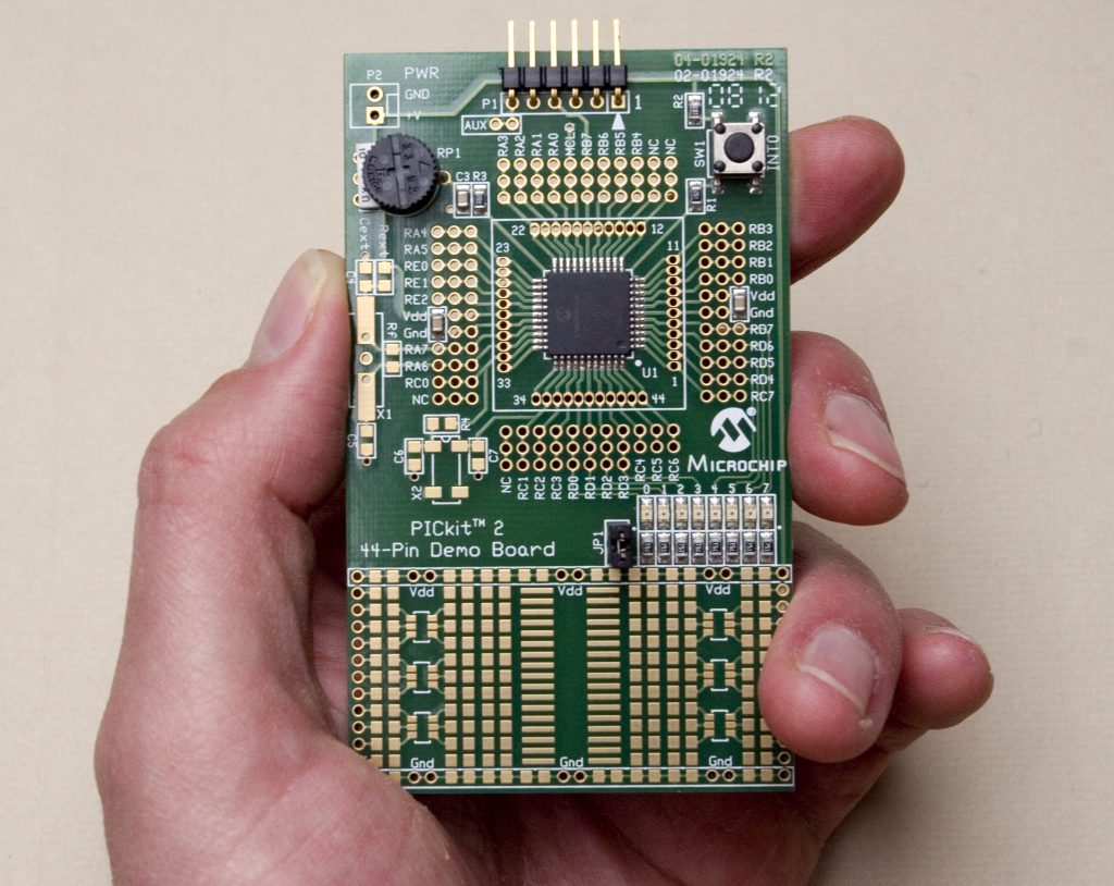
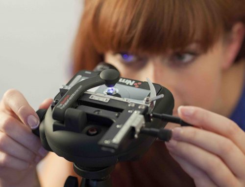
A Microchip PICkit 2 PIC programming board. A square PIC is hard-wired to the centre of the board. Designers can use the board to try out programs
Neat Tricks
One of things Brian realised while writing code for EPROMs, and later PICs, was that they could be made to do several jobs at once, if programmed in a particularly precise way. Having one processor do the job of two was clearly a good thing, as it cut down on circuit board real-estate, the use of chips and the associated components. By doing more with each processor, production costs could be reduced and functionality was optimised.
“I was a hardware engineer, doing hardware digital design, and just using microprocessors as another means of achieving what I wanted,” says Brian, “but I was doing things that were somewhat unorthodox; things that a software engineer would never dream of doing. They think of code, they don’t think of the hardware. I was coming in from a certain point of view and making the processor do two jobs at once.
“I was counting time round loops whereas software people would use a separate timer. For example, I had a product that was writing to a seven-bar LED display, and outputting a signal at the same time and I got my timing to fit in with the writing of the display. That was most unorthodox and no software engineer would dream of doing such a thing, but it meant that I could do two things at the same time with one chip rather than putting two chips in there, one to do one job, one to do the other.
“Even later on with the PIC I was doing similar things. I had three UARTs – universal asynchronous receiver/transmitters – running in a PIC, when in fact there was only one standard UART built in there! Two of them were driven by me counting time, so I was doing it all in the same chip by writing software UARTs. Otherwise we would have had to do what a software engineer would do, which is buy some extra UART chips. That would have used up more in/out pins on the PIC and we didn’t really have them to spare. We had two other boards with PICs on and we needed to talk to them, plus I had another communication path from another process. So the PIC in question needed to talk to three things and I didn’t want to have three UARTs.”
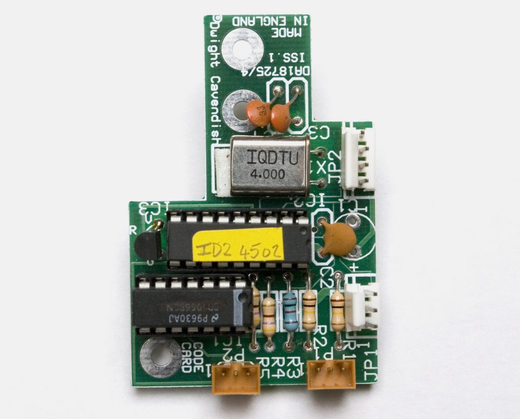
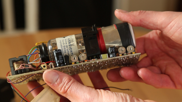
This Dwight Cavendish board was made to fit inside video machines. The PIC is the chip with a yellow label on it
Writing DIY UARTs and Registers
Brian explains a little more about UARTs and how they work, describing how he went about writing his own software UARTs to run on a single PIC processor.
“A UART is basically a register. You load the byte you want to transmit into the UART register, tell it to send the byte, and it will spew it out serially. If it is the other way round and you are receiving data, when a complete word comes in you are notified by a flag that it has arrived and you get a whole word in the register. You ask it if it has the data yet, and it says ‘Yes I have, here it is.’
“If you create a software UART you are not using that register; you write out all the code and clock in every bit. You have one in/out pin, and you toggle out each bit with it. So, for example, when you are dealing with an eight-bit word, there will be a start bit followed by the eight bits, then maybe a parity bit to check for errors, and then a stop bit. Parity bit is optional on the RS232-type communication protocol, although some other systems or designs might insist on it being present.
“So what you do is time out the bits by writing a little wasting loop and outputting the code, bit by bit, as the loop cycles. So, for example, if you have got an eight-bit word, the first bit is a nought and for that you’d output a low on that pin, and keep it low for one bit-time. That would be one tenth of a millisecond, or something like that. The pin will stay where it is for evermore, until you tell it something else. So once you have made it go low, you count out a bit time by going round the little loop. And you know it will take exactly that amount of time because you know the crystal frequency and how many microseconds it takes to go round the loop.
“After you’ve counted out that time you can output the next bit. If it’s a one you make it go high. Then you count out another bit-time and you keep going until you’ve gone through all eight bits. At the end you might do a parity check, or simply create a stop bit, which is a one, so for that you just keep high.
“When you have finished with that you go and get the next byte you want to send and do the whole thing again. But the disadvantage is that while you are counting the time you are dedicated to sending the data and you can’t do any other jobs, whereas if you have a UART you just send the byte to the UART and tell it to send it and while it is doing that you can go off and do other jobs.
“So when you do it with software you have to make sure you are not going to do any other tasks. If you have a system that allows interrupts, which usually force you to do a job immediately, you have to switch them off.
“On the opposite way round, when the stream is coming in, you have a bit of code that detects the first edge of a byte. You are usually looking for a high going to a low, which means that a start bit has occurred, so you have got to keep polling it all the time.
“If a start has occurred, you wait half a bit time which takes you to halfway through the start bit. You know the start bit is low so you just ignore it. After that you count another whole bit time and that takes you halfway through the first bit. Then you read that pin to see if it is still low or has changed to high. If it is high it is inputting a one, if it is low it’s receiving a nought. Then you simply carry on until you have gone through all eight of them and then check when it has finished that a stop bit has occurred.
“So whether you are sending or receiving, you have to stop what you are doing and count out a time and there’s absolutely no way a software guy would ever do that. It would be an anathema to them.”
Instead of working in an assembler language peculiar to a particular PIC, a more conventional way of working would be to use a general-purpose and widely-used language like C, which a large proportion of other software engineers could understand immediately. Brian explains why he mostly chose to stick to assembler.
“Creating code with assembler rather than in C means that you do things that you wouldn’t normally do in C. I’m not saying you couldn’t do it in C, but you wouldn’t tend to and C would compile it in different ways. If you are counting microseconds around a loop that you have created, for example, C will compile it in its own way and you will end up with different times.
“You can import some assembler into C language and tie it down, but when you write down the instruction set in assembler you are totally in control of what’s going on inside the microprocessor. If you write in a higher language, it might decide to cut out some lines of code and minimise what you have done because it can’t see the point in it. It will do what it thinks will achieve the same thing. So you are not in control.
“Most companies like to write in a higher-level language like C or C++ for software maintenance purposes. If all engineers are working with a language that is more commonly used then another engineer can maintain another engineer’s software. When you start writing it in assembler and doing funny little things it starts to become dependent on that one engineer debugging it. Other engineers can’t easily understand what you are doing, so from a software maintenance point of view it is not a good way to go and the cost of software maintenance can become very important. So companies tend to work a different way to what I was working.
“I started off on a certain course and got rather proficient and expert at it and you tend to keep going the way you are going because you’ve got so good at it. You don’t particularly want to change and there was an element of that with me.
“Later on, when I got to Crystal Vision where they were using the Toshiba H8 16-bit processor, I was writing stuff in C language, using a compiler and more orthodox methods.”
Stewart Wilson’s Burner exhibition flyer front
The Burner Project
In 1993, installation artist Stewart Wilson approached Dwight Cavendish to find out if they could design and supply the hardware he needed to show a multi-screen film he’d made. The artwork, titled Burner, comprised a wall of television screens which, as a whole, showed a mesmeric film of flames leaping against a night sky backdrop. Stewart needed to automate the playing of the film, but each television screen was driven by its own video player and tape, so it was necessary to have a control system which could play, stop and rewind all the machines together, over and over again.
Backed by a commission from the Cambridge Darkroom and the Harris Museum and Art Gallery in Preston, and armed with funding from the Arts Council, Eastern Arts Board and Cambridge County council, Stewart was looking to purchase a custom-designed system to power Burner. Brian was interested in the idea and immediately took it upon himself to try and adapt a video system to suit Stewart’s requirements. Brian explains how he came to be involved.
“Stewart came along as a customer and was going to buy some hardware off of us and needed some special software. He visited me at work and we had a discussion, then we had lots of further talks on the phone. Initially he was trying to get funding, but when it eventually came through he ordered a certain amount of hardware and there was some money built in there for the software development. In all it was a few thousand pounds, I think.
“Without really talking it over with the boss, I undertook to do an extensive amount of software development. I got carried away and I was actually doing a lot of it at home in my own time, so it was just a personal thing. I did all the costing and came up with the quote, but I didn’t have a whopping amount of money in there for software.
“Stewart had created all these separate videos and must have spent hours on an editing machine. It was a lot of work. It was something like 10 to 20 screens with a video machine connected up to each television. So when all that started playing, all these monitors would create this flame pattern and were synchronised with each other to some extent.
“What we wanted to do was start them all off from the same point and iron out the variations you get from one machine and tape to another, bearing in mind that on one of these tapes you might have 10 seconds of blank tape at the start and another might have 12. And one VCR might lace up the tape faster than another one. The software I was working on at home was a routine which allowed you to iron all that out.
“We knew which tape would go in each machine so the plan was for each machine and tape to have their own individual program and what I was going to do was use the non-volatile memory to store the cue-up time for each of them. So there was going to be a little routine before the film started during which they were all going to get cued up.
“For example, it might play one tape for 15 seconds, and another for 13 seconds to get them lined up.
“The hardware I was using was one of the first products where we had with an LCD on the front displaying time and so that could be used as part of the calibration. I designed it so that Stewart could calibrate each one and store the setting in the memory location for each machine and tape combination. I think you played the tape and watched the screen until you got to the point where it began, then noted that time, or maybe even the hardware measured it, and then it was stored in the non-volatile memory.
“But when I got something working and he came over with a video machine, we tested it out and found that I had to do something slightly different on the code. The problem was he couldn’t get the machines he thought he was getting. He was using domestic VCRs that were loaned to him and they wouldn’t quite work the way he wanted. I’d done this special software but because of this snag, in the end we had to abandon that and they all got started off at the same time and we just trusted that they were more or less together!
“If one was running a second faster or slower, nobody noticed because what you were looking at wasn’t that precise. For what he was trying to achieve the timing didn’t really matter and I can’t believe that anyone would look at all these flames licking around and think, ‘That one over there is running a bit slow compared with the others.’ It was so random the way the flames went up.
“So in the end the system would play it all, stop, and then rewind all the tapes; just like a regular repeating play program that I’d done with other products. In a way it wasn’t far from the sort of things we were normally doing in terms of controlling VCRs; he was just a bit different from the normal customer we would be dealing with.
“We also did the metal work for him, to his design specification. He wanted a rusty look – he didn’t want paint on the metalwork. Then at the end when the thing was over the commissioning organisations found themselves in possession of this hardware that they didn’t really want, so we bought some of it back from them.
“I think it all went fairly successfully. The equipment worked and did what he wanted. He went round the country and to Scotland with it, setting it all up in each venue.” TF
Stewart Wilson’s Burner exhibition flyer back
Part 1 of Using EPROMs and PICs can be found here: Part 1


