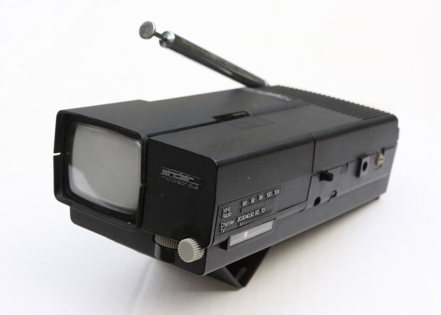
TV1B Prototype with FM radio
The Chips That Failed
By about 1973 Adrian Espin had proven – and it did take him a while to convince the management, who didn’t want to believe it – that the TV chip set of ICs we’d been waiting for was a non-starter. Basically, it was never going to work well enough to make a television the way the company wanted to. Adrian had found problems, which he’d tried to solve for quite a while, but couldn’t. So there was a decision to redesign a new chip set.
A lot of new people had come into the company because of the success of the calculator, and they were saying “Why do we want to mess around with that for?”, but Sinclair still thought it viable and was adamant that it was what we were going to do.
But sometime around 1974, Sinclair was starting to lose control of the company because the National Enterprise Board was putting a lot of money in to support it. So, although there was going to be a new television and newly designed chip set, the NEB specified that the development be left to the team of engineers headed by Adrian Espin.
The team included John Brown working on the tuners. He joined around 1974 and left in 1976, at which point I took over the tuner design. I remember having to make trips to AB Electronics in Merthyr Tydfil, Wales, where they were manufactured. I also recall, on one occasion, my driver being an employee called Mike Black, who had previously ran Cambridge Audio, based elsewhere on the mill site. I even bought a set of speakers and cabinets from him in 1972 and still have them today. Mike went on to form Black Star Instruments and was very successful.
We also had John Tothill in the team, who joined about a year after me, working more on the audio side, and I was working on generating the EHT, line and frame oscillators. I designed an IC for it and there was another IC designed by Adrian Espin, both of which were made by Texas Instruments, mainly because we had good links from when Adrian used to work for them. We sold hundreds of thousands of these chip sets, so it was good business for them. I wasn’t involved in the financial side but presumably we were paying for the tooling and any other monies that were needed to set the thing up.
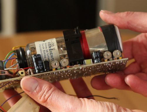
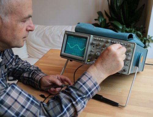
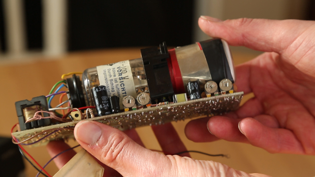
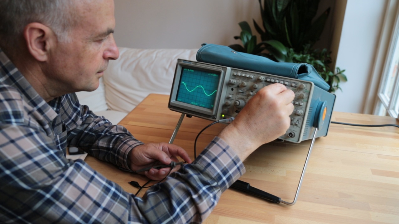
Incidentally, Sinclair Radionics also made a little oscilloscope using the same tube we had in the television, and used the chip I designed as part of it. I still have a prototype that I worked on. If you look at the photograph of the tube you can see the mu-metal strip taped around the glass. That protects it from interference from the earth’s magnetic field, which otherwise might pull the cathode beam out of alignment!
Our brief was that we were going to make the television a multi-standard set that would work in all the major countries, including the USA, Europe and England. It was to be black and white and the screen dimension would be about two inches across. That became the TV1 which came out in about 1976. I suppose I was working on it for about a year to a year-and-a-half full time.
Marketing The TV1
By the time the TV1 was on sale, Adrian Espin had moved out of R&D into the engineering and production department so I was effectively the chief engineer for the television. Like the hi-fi, television wasn’t the main business of the company; it was still the calculators and the little digital watch that had come out. I didn’t work on the watch, but someone who did was Chris Wilding, who eventually left to become a director of Thurlby Thandar.
Sinclair Radionics manufactured quite a lot of TV1s but didn’t sell as many as they had hoped to because it was too expensive, so the follow up, the TV1B, was basically a cost reduction. We had made the TV1 a multi-standard set, but because that required a VHF and UHF tuner in each one, and in the UK you only need a UHF tuner, it was decided we’d have just one tuner in the TV1B and save a lot of money. So we did a UK model and then separate models – the TV1C and TV1D – for other parts of the world.
I do remember that Sinclair somehow got involved at that stage and was looking at ways of getting rid of the IC that I had designed and replacing it with two or three transistors, as if they would do the same job! There were about 80 transistors in the IC and he wanted to take it out and replace it with about two! That IC was doing a lot of jobs, but it was decided that some of the bits around it could be cut down. But you couldn’t just go hacking bits out because the IC was driving the chips that went around it and they were integral, so I made suggestions as to where I felt we could do a bit of cost reduction, as I’d gained a bit more experience at that point. So there was a little bit we could do. We also saved by putting the TV1B in a molded plastic case, and had a good mechanical engineer called Vic involved with the design of that.
The TV1B I still have is a prototype with a radio built in. They were thinking about sticking a radio in at the time. The TV1 didn’t sell well so they were trying all sorts of things to help sales, and the built-in radio was probably one of them. The radio had the same FM tuner design, with exactly the same transistors, as the discontinued hi-fi tuner I spoke about earlier. It actually works pretty well as a portable radio with a little aerial coming off of it. When you have a little antenna sticking out you don’t pick up more than a couple of hundred micro Volts, so it doesn’t cross-modulate like it would if receiving large signals from a fixed aerial installation on the top of a house.
One of the jobs I was given was to see if we could sell the television in France, where they had a different system. There wasn’t a problem with power as the TV1B ran from either a little mains adaptor or batteries, but for the sound carrier, they used a system which had similarities with the old 405 line TV system in the UK. That signal was still being transmitted back in 1976/77 to cater for those people who were still out there using those sets. There was a cutoff date, but up until that point I used the 405 line signal to test circuitry and do some development, because then I only had to make a small change for it to work in France.
I actually went over to Paris with a prototype in my bag to try and test the set with real signals, and met some agents we had over there. It worked, but I think there was some sort of problem it had when it was receiving more than one signal. But they didn’t sell any and so it didn’t come to anything, as far as I’m aware.
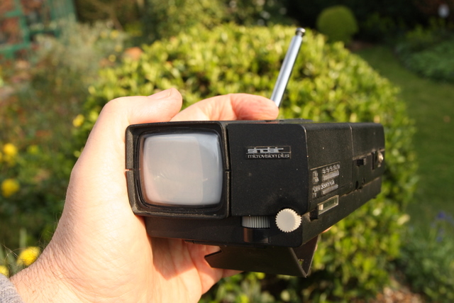
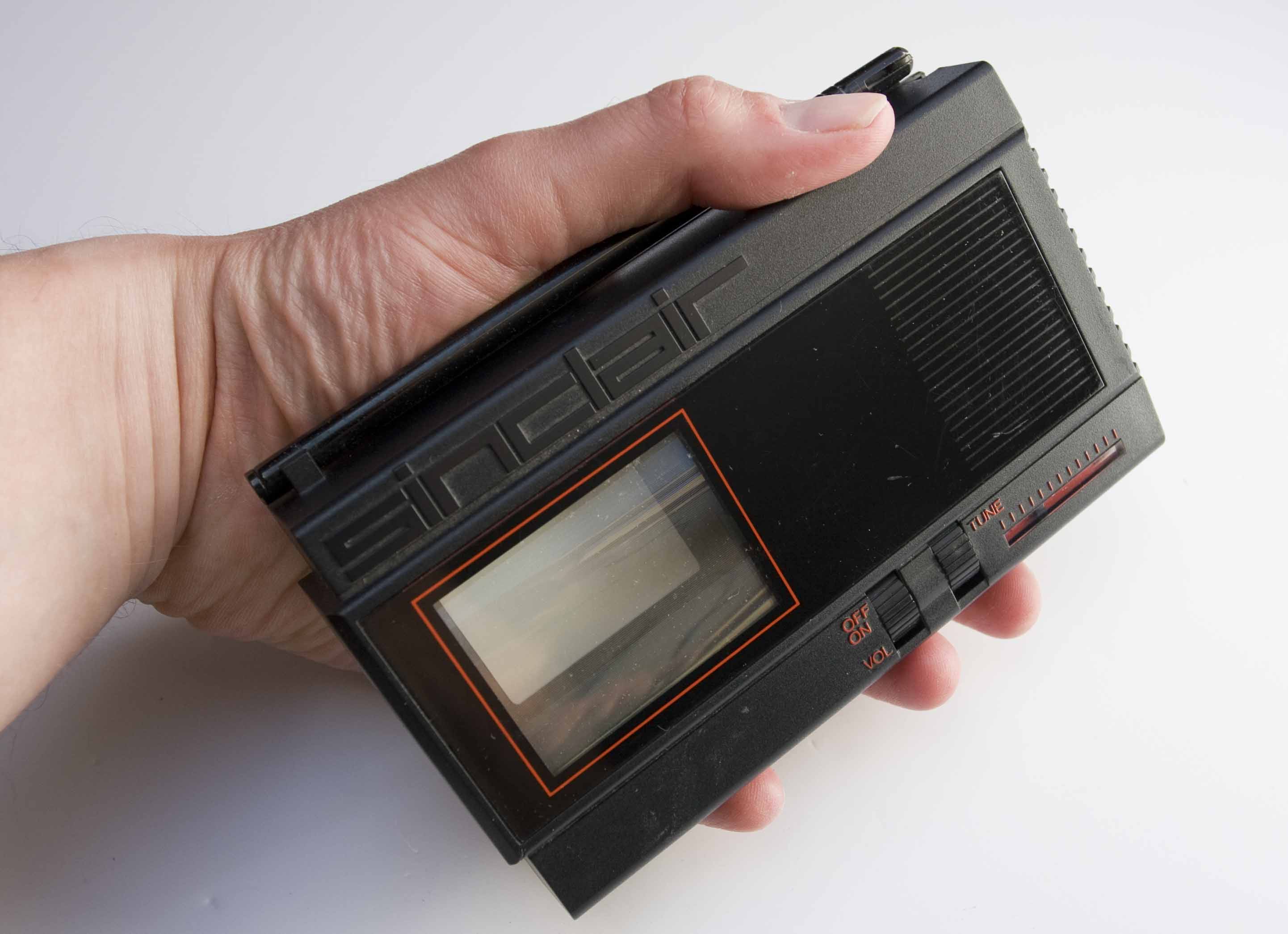
TV1B working Prototype
Flat Screen Dream
Sinclair eventually produced a flat screen version of the television years after I left, but work on that started in the ’70s. From about 1974 onwards there was a little tube prototype-building lab set up in the bottom of the mill, where they had a vacuum pump for removing air from tubes. Also down there were some engineers who’d possibly previously worked for Thorn or some other UK tube manufacturer. Whatever the company, they were experienced engineers, practical people, who had previously been involved in the mass production of television tubes.
The television tube manufacturing industry in the UK was dead as all the tubes were being made in the Far East, even back then. So there were all these talented people around with experience and Sinclair had recruited a couple of them – one of whom I remember was a chemical engineer.
Sinclair wanted a new model television that would be much more compact, smaller and flatter than the TV1B. The design was not too far away from what you might have today on a mobile phone with an LCD, in terms of its proportions. They were working towards perfecting a cathode ray tube that was side on to the screen and the electron beam bent through a right angle.
The trouble was that when you scanned it, it didn’t produce a rectangular picture, because at the far end it would deflect further than at the nearest end giving you a trapezoid shaped image. The trick was to electronically change the voltage to make the saw-tooth waveform into an ‘S’ shape, basically, so that it would compensate.
I got involved in taking the chips and circuitry from the normal TV1B television and cobbling on some extra circuitry to bend its beam. I used the same chip set and IC that I designed and then injected some extra waveforms at the appropriate points; pinching a waveform from somewhere, amplifying it and shoving it in somewhere else to do the correction.
It gets complicated because when you bend out the narrow side, it doesn’t go square, but tends to bulge a bit in the middle, so then you have to correct that with another waveform, and there were various other second order effects to correct for too. But eventually you could get the picture right.
The TV80 was the culmination of Sinclair’s ‘flat screen’ dream, but that’s another story…
Magnification Tricks
What we also did was have a two-times magnification lens on the front so that the beam didn’t have to deflect quite so far in the first place. It meant that your angle of view was cut down, so if you had your head too far to one side you wouldn’t be able to see the image, but it wasn’t too bad a compromise. Pulling the beam out using waveforms would have required a bigger tube and doubled or quadrupled the amount of power needed to deflect the beam.
Also, the distortion is less if you are deflecting less, so you don’t need so much correction. Everything builds up against you if you do it with waveforms, so optically magnifying the screen really helped reduce the power requirements of the circuit.
There were several tube designs made in the lab at the mill but they all suffered from the same sort of problems I’d experienced several years before with the coffin-shaped tube. It was a case of getting one with the beam in the middle, and not off to the side by a few millimeters because of poor construction. But eventually we got one that was useable.
The flat screen design started as just another R&D exercise, but what Sinclair needed was to something to sell and flash around to people to raise money. In the long run the production required some new chips and semi-conductors and another IC possibly made by Texas Instruments, because he wasn’t going to do it with discrete components. He was going to make a special circuit to deflect the beam and drive the tube. Also, until you get the tube right there is no future, and all that was going to need a lot of investment. As far as I’m aware, to get from the bits and pieces that I saw back then, in 1978, to the point where it could be run off as a mass produced production item, there needed to be an injection of many millions of pounds.
So we put the tube into a make-believe box, probably carved out of balsa wood and styled to look real, and squeezed the circuitry around the sides. When you had it in your hand it looked like you had something that had come out of the factory. It was a bit bigger than it should have been but we had something that didn’t look too bad. We had a little PP3 battery, or something of that type, powering it all, but this extra business with the screen was eating up the power, so it was only alright if you didn’t run it for more than 10 minutes! We were just putting circuitry in there to make it work, not to save power.
So my involvement was getting that prototype to work and it did produce a picture. But the bits that went into the final item, when it was eventually made round about 1984, were considerably different to the electronics that I put in the prototype in 1978. I can only assume that that the funding became available off the back of the success of the ZX Spectrum, and all this extra deflecting analogue circuitry – which I mocked up using resistors and capacitors – they eventually did by storing the waveforms digitally in ROM so that they could rapidly read out the information and turn into an analogue signal. Of course, that was the plan right early on, but the technology was only just about there to do it. TF
Part 1 of Engineering for Sinclair can be found here: Part 1
Part 3 of Engineering for Sinclair can be found here: Part 3